I inherited a Commodore PET 2001 computer which I think dates from 1977. This computer (along with the Apple II and TRS-80) is historically interesting as it is considered to be one of the first computers for the "normal person" - somebody could buy it from a shop, plug it in and be automating their business and optimising their production schedules - but more likely, playing tax-deductible "space invaders" while "working".
I think it looks great in a retro-1970s-futuristic way. Not quite as futuristic as the DEC VT05 terminal (my favourite piece of retro computer product design) but still very nice. (The moniker "PET" supposedly stands for "Personal Electronic Transactor" if you want more 1970s futurism.)
 Photo: The Commodore PET 2001 with its characteristic angular steel case.
Not to boast or anything, but this was the "fancy" model of the time which had a whole 8 kilobytes of memory - an upgrade from the basic model with 4k bytes. Eat that with your modern computer with - erm - a million times more. Oh.
Much is written online about the PET (Wikipedia) so there's not much for me to add here in terms of its history.
A few years ago I repaired it and got it working again - maybe some day I will blog about this. I noticed recently that the ROM chip which generates the character display is beginning to fail. This seemed like an excuse for a far larger distraction - let's re-create a whole computer from scratch!
I decided that it would be interesting to emulate the whole circuit board using a tiny modern microcontroller. I've been curious to use the programmable peripherals in the Raspberry Pi Pico to generate video signals, so this sounded like a good thing to try. I've got it working with a VGA monitor, but plan later to get it working with the original PET monitor.
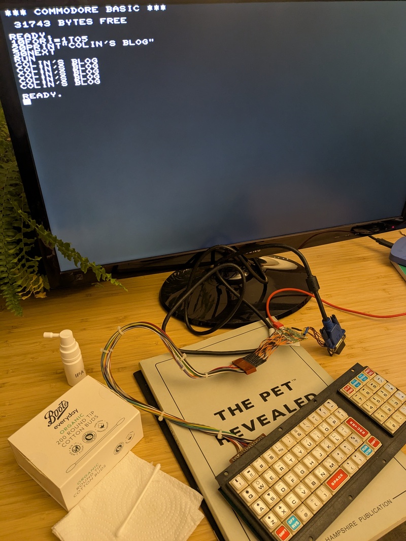 Photo: A Pi Pico, a PET keyboard, a VGA monitor and some dubious soldering and we have a DIY PET! Keyboard cleaning materials also in view.
I had to piece together some information, so putting a summary of my notes here in case anyone else is interested. I'm sorry that this is a bit of a jumble, but it does show nearly all the code and so might be useful if someone else wants to emulate a PET or something else on a Pi Pico.
What's inside a PET?
Compared to today there wasn't much to an old computer. The PET 2001 contained:
- A 6502 8-bit Microprocessor running at 1MHz.
- 4/8 kilobytes of static RAM.
- 14 kilobytes of ROM.
- A 40x25 monochrome CRT screen with inverse video and "PETSCII" graphics characters.
- 3 IO chips (a 6522 "Versatile Interface Adapter" (6522 Datasheet) and two 6520 "Peripheral Interface Adapters" (6520 Datasheet).
- Discrete logic chips to generate a video signal, connected to a character generator ROM and 1k video RAM.
- A keyboard.
- A cassette recorder.
- Expansion slots - a IEE488 "GP-IB" or "HP-IB" interface bus, a parallel IO port, a second cassette port and a memory expansion port.
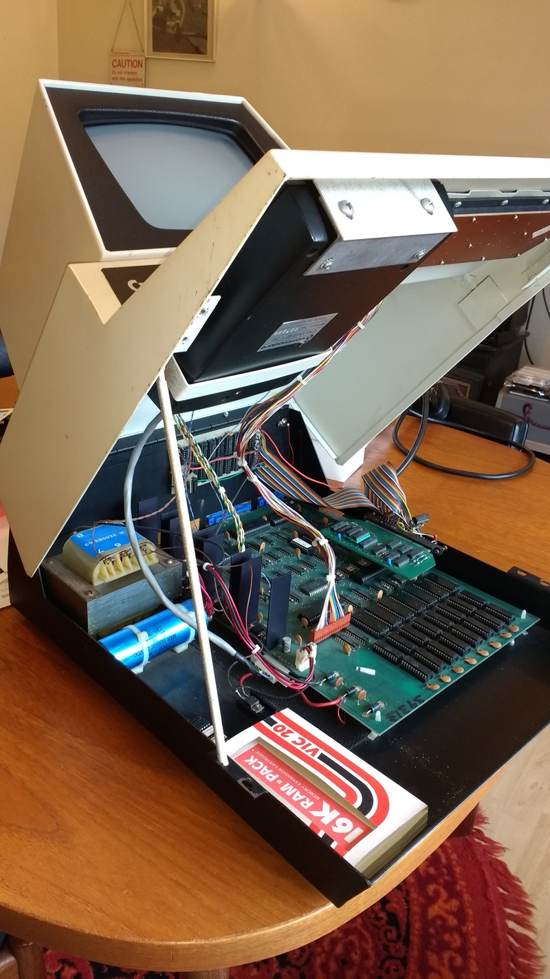 Photo: The whole lid of the PET lifts up for maintenance, and can be propped open like a car bonnet - this is the best bit of the PET. My one has additional memory expansion boards added at the back and right hand side, which aren't original.
Later PET designs (like the 8032) used dynamic RAM and a 6545 CRT controller IC, but the whole PET range was broadly similar.
The PET 2001 memory map:
| Address from | Address to | Description |
|---|---|---|
| 0x0000 | 0x7FFF | 4k to 32k RAM |
| 0x8000 | 0x83E7 | 1000 bytes video RAM |
| 0xE810 | 0xE813 | PIA1 - 6520 (4 registers) |
| 0xE820 | 0xE823 | PIA2 - 6520 (4 registers) |
| 0xE840 | 0xE84F | VIA - 6522 (16 registers) |
| 0xC000 | 0xFFFF | ROM |
References
These documents were really helpful in letting me figure out how the PET works:
- The PET circuit diagram - zimmers.net - PDF
- The PET revealed book - I have a physical copy, but online PDF
- Andre Fachat - Commodore programming model
- BASIC2/4 memory locations list
What's the minimum necessary to emulate a PET?
You can make a PET in software as following:
- Get a 6502 emulator.
- Have an array representing the address space of the 6502.
- Load the ROM images into this array.
- Have some kind of 40x25 display.
- Intercept writes to the character RAM and update the display accordingly.
- Intercept writes and reads to one of the PIAs and read any keypresses.
- Intercept a read to the VIA and return a fake value.
- Call the 6502 IRQ interrupt 60 times per second.
So: Let's do it. I now show nearly all the code necessary to emulate a PET, with some descriptions.
Step1) 6502 emulator, main loop and memory decoding
I used the fake6502.c emulator.
We need to allocate an array to represent the PET RAM. The PET only needs 8k of RAM, but it simplifies the emulator to map the whole 64k processor address space into RAM:
// This array includes RAM and ROM - ROM copied into here at start
uint8_t cpu_address_space[64*1024];
You need to implement two functions which are called from the emulator to read and write memory. The 6502 maps IO to memory, so IO reading and writing is also handled here.
Read fakes a PIA chip (for keyboard reads) and a VIA chip (to determine if the screen can be updated).
uint8_t read6502(uint16_t address) {
    // Intercept keyboard reads
    if ((address >= 0xE810) && (address < 0xE81F)) return read_PIA1(address);
    // We only care about one register in the VIA
    if (address==0xE840) return 0; // Pretend VBlank is active to write to screen

    return cpu_address_space[address];
}
Write intercepts video RAM writes, and keyboard row writes.
void write6502(uint16_t address, uint8_t value) {
    // Intercept video memory writes
    if ((address >= 0x8000) && (address < 0x83E8)) write_video_mem(address-0x8000,value);
    // Intercept writes to the keyboard
    if ((address >= 0xE810) && (address <= 0xE81F)) write_PIA1(address, value);

    cpu_address_space[address] = value;
}
The whole "main" loop of the emulator initialises the keyboard and video parts. It copies the ROM, and resets the processor.
It then spends the rest of time making the 6502 execute the next instruction, while periodically calling the interrupt.
int main() {
    VIDEO_init();
    init_keygpio();

    // Copy the ROM into the "RAM" space at 0xC000
    // Although this needs more RAM we have enough,
    // and it simplifies the lookup.

    memcpy(cpu_address_space+ROM_START,MACHINE_ROM,ROM_SIZE);
    reset6502();

    int count = 0;

    while (1) {
        exec6502();
        count++;

        if ((count % PERIOD_60HZ) == 0) {
            irq6502();
        }
    }
    return 0;
}
Step2) ROM
Bo Zimmers has ROM chip images available from their web site. I download these and combine them into a single binary image, leaving a 2k blank GAP where the IO memory lives.
I then use the UNIX 'xxd' utility to create two 'C' header files - one representing the processor ROM ('allroms.h') and the character generator ('chargen.h')
mkdir -p ROMS/BASIC1 && cd ROMS/BASIC1

# Download the ROM images...
wget http://www.zimmers.net/anonftp/pub/cbm/firmware/computers/pet/rom-1-c000.901447-01.bin
wget http://www.zimmers.net/anonftp/pub/cbm/firmware/computers/pet/rom-1-c800.901447-02.bin
wget http://www.zimmers.net/anonftp/pub/cbm/firmware/computers/pet/rom-1-d000.901447-03.bin
wget http://www.zimmers.net/anonftp/pub/cbm/firmware/computers/pet/rom-1-d800.901447-04.bin
wget http://www.zimmers.net/anonftp/pub/cbm/firmware/computers/pet/rom-1-e000.901447-05.bin
wget http://www.zimmers.net/anonftp/pub/cbm/firmware/computers/pet/rom-1-f000.901447-06.bin
wget http://www.zimmers.net/anonftp/pub/cbm/firmware/computers/pet/rom-1-f800.901439-07.bin
# ...and the character generator ROM
wget http://www.zimmers.net/anonftp/pub/cbm/firmware/computers/pet/characters-1.901447-08.bin

# Make a blank 2k for the IO space
dd if=/dev/zero of=blank2k.bin bs=2048 count=1

# Join the ROMs together, including the gap
cat rom-1-c000.901447-01.bin rom-1-c800.901447-02.bin rom-1-d000.901447-03.bin rom-1-d800.901447-04.bin rom-1-e000.901447-05.bin blank2k.bin rom-1-f000.901447-06.bin rom-1-f800.901439-07.bin > allroms.bin

# ... and turn into C header files.
xxd -i characters-1.901447-08.bin > chargen.h
xxd -i allroms.bin > allroms.h
These are then included in the C source code:
#include "ROMS/BASIC1/chargen.h"
#include "ROMS/BASIC1/allroms.h"

// Point these to the appropriate ROM arrays
const unsigned char* CHAR_ROM = characters_1_901447_08_bin;
const unsigned char* MACHINE_ROM = allroms_bin;

static const uint16_t ROM_START=0xC000;
static const uint16_t ROM_SIZE=16384;
…'MACHINE ROM' is read above at startup, in the 'main' function above.
Step3) Keyboard
The keyboard is wired as a matrix of 10 rows and 8 columns which I wired to Pi Pico GPIO pins. "The PET revealed" page 124 gave me the details I needed.
The keys map as follows:
| Row | PB0 | PB1 | PB2 | PB3 | PB4 | PB5 | PB6 | PB7 |
|---|---|---|---|---|---|---|---|---|
| 0 | ! | # | % | & | ( | ← | clr | crsr left |
| 1 | " | $ | ' | \ | ) | crsr dn | inst/del | |
| 2 | Q | E | T | U | O | ↑ | 7 | 9 |
| 3 | W | R | Y | I | P | 8 | / | |
| 4 | A | D | G | J | L | 4 | 6 | |
| 5 | S | F | H | K | : | 5 | * | |
| 6 | Z | C | B | M | ; | ret | 1 | 3 |
| 7 | X | V | N | , | ? | 2 | + | |
| 8 | shft | @ | ] | > | shft | 0 | - | |
| 9 | rvs | [ | spc | < | run | . | \= |
http://cbmsteve.ca/petkeyboard/index.html gave me the keyboard pinout.
I soldered 18 wires from a 0.1" header pin to the Pi Pico GPIO pins ( pico pinout) and defined a GPIO mapping as follows:
| Pin | Colour | Function | GPIO |
|---|---|---|---|
| 1 | N/C | Gnd | |
| 2 | N/C | Key | |
| 3 | Blk | R9 | GP17 |
| 4 | Wht | R8 | GP16 |
| 5 | Gry | R7 | GP15 |
| 6 | Vlt | R6 | GP14 |
| 7 | Blu | R5 | GP13 |
| 8 | Grn | R4 | GP12 |
| 9 | Yel | R3 | GP11 |
| 10 | Orn | R2 | GP10 |
| 11 | Red | R1 | GP9 |
| 12 | Brn | R0 | GP8 |
| 13 | Gry/Wht | C7 (PB7) | GP7 |
| 14 | Vlt/Wht | C6 (PB6) | GP6 |
| 15 | Blu/Wht | C5 (PB5) | GP5 |
| 16 | Grn/Wht | C4 (PB4) | GP4 |
| 17 | Yel/Wht | C3 (PB3) | GP3 |
| 18 | Orn/Wht | C2 (PB2) | GP2 |
| 19 | Red/Wht | C1 (PB1) | GP1 |
| 20 | Brn/Wht | C0 (PB0) | GP0 |
The schematic diagram of the PET shows that the PB0-PB7 lines are connected via pull-up resistors. Fortunately the RP2040 microcontroller in the Pico has these built in, so they can be enabled in software:
#define GPIO_IN_BEGIN 0
#define GPIO_IN_COUNT 8
#define GPIO_IN_MASK 0xff

#define GPIO_OUT_BEGIN 8
#define GPIO_OUT_COUNT 10

void init_keygpio() {
    for (int gpio = GPIO_IN_BEGIN; gpio < GPIO_IN_BEGIN+GPIO_IN_COUNT; gpio++) {
        gpio_init(gpio);
        gpio_set_dir(gpio, GPIO_IN);
        gpio_pull_up(gpio);
    }

    for (int gpio = GPIO_OUT_BEGIN; gpio < GPIO_OUT_BEGIN+GPIO_OUT_COUNT; gpio++) {
        gpio_init(gpio);
        gpio_set_dir(gpio, GPIO_OUT);
    }
}
The PET writes to PIA1 when it wants to select a keyboard row. It does this 60 times a second, from IRQ interrupt routine.
void write_PIA1(uint16_t address, uint16_t value) {
    switch (address) {
        case 0xE810:  // PIA1_PA
           set_keyrow(pia1_pa_out & 15);
...
}
This is decoded by a 74145 BCD to decimal decoder into the 10 keyboard row select lines. (Note - this has inverting outputs so is normally high, but with an active low output.) So the selected keyboard line is pulled low. I loop through each keyboard row output, setting or clearing it.
void set_keyrow(uint8_t keyrow) {
    // All GPIOs must be high, apart from the selected one which should be low
    for (int gpio = GPIO_OUT_BEGIN; gpio < GPIO_OUT_BEGIN+GPIO_OUT_COUNT; gpio++) {
        if (keyrow == gpio-GPIO_OUT_BEGIN) {
            gpio_put(gpio,0); // Selected row, so clear
        } else {
            gpio_put(gpio,1); // Not selected row, so set
        }
    }
}
An optimisation might be to use bit-twiddling - something like
0x3ff^ (1<<row)
…but the above loop is probably simpler to understand.
When the PET wants to read the selected column, it reads from PIA1, which causes the bottom 8 Pico GPIO pins to be read:
uint8_t read_PIA1(uint16_t address) {
    switch (address) {
         case 0xE812:  // PIA1_PB
            if ((pia1_crb & 0x04) != 0) {
                /* Clear IRQs in CRB as side-effect of reading PB. */
                if ((pia1_crb & 0xC0) != 0) {
                    pia1_crb &= 0x3F;
                }
                return read_keycolumn_gpios();
...
}

uint8_t read_keycolumn_gpios() {
    return gpio_get_all() & GPIO_IN_MASK;
}
…and that's the keyboard!
Step4) Video
This is the interesting bit. I decided to use a VGA monitor for initial debugging for two reasons:
- First, I had one to hand but would need to disassemble the PET - and I need to have some gym sessions before I'm capable of lifting the PET…
- Second, there are lots of tutorials out there already and code that can be reused for VGA.
I used Van Hunter Adams VGA Driver for RP2040 tutorial for this, which I recommend reading. The way this code works is really neat. Once the PIO and DMA controllers have been set up the chip generates video with no software needed. Nice.
I modified the Van Hunter Adams code slightly to output monochrome video, and one bit per pixel - opposed to colour. Most of the video code I show is as in the tutorial - I didn't write the clever bits!
Hardware connections:
| Pico GPIO | Function | VGA pin |
|---|---|---|
| 18 | Video out | Red,Green,Blue |
| 19 | Vertical sync | VSYNC |
| 21 | Horizontal sync | HSYNC |
The single video output is connected to the red,green,blue signals in parallel to generate 'white'. It is connected via a 100 ohm resistor to correct the voltage levels for analogue video. The Hsync and Vsync signals were connected via 47 ohm resistors.
The code works as follows:
Define a bitmap area of RAM - 640 by 480 pixels, with 8 pixels per byte - so 640*480/8. Writing bits to this array makes pixels appear on the screen.
#define TXCOUNT 640*480/8

unsigned char vga_data_array[TXCOUNT];
Define a function which is called when the processor writes to video RAM. 'write video mem' is called from 'write6502' above. It decodes the x,y, position and calles 'write char' which looks up the character in the character ROM, and then updates the video memory bitmap defined above. So write char turns characters into pixels, using the character ROM as a "font".
void write_video_mem(uint16_t video_address,uint8_t value) {
    uint16_t y = video_address/CHARACTERS_PER_ROW;
    uint16_t x = video_address%CHARACTERS_PER_ROW;
    write_char(x,y,value);
}

void write_char(int x, int y, char character) {
    for(int row=0;row<ROWS_PER_CHARACTER;row++) {
        int romaddress = ((character & 0x7f) << 3) | row;
        //if (graphics_characters)
        //    romaddress |= 1024;
        // Read the character ROM
        int romvalue = CHAR_ROM[romaddress];
        int inverse_video = character & 0x80;
        if (inverse_video)
            romvalue ^= 0xff; // Invert the ROM

        // Update the video RAM
        // Each address holds 8 bits which is 1 character, so we can
        // just add x
        int vram_row=(row+y*ROWS_PER_CHARACTER)*STRIDE;
        int vram_address=vram_row+x;

        vga_data_array[vram_address]=romvalue;
    }
}
The clever stuff is in the PIO code:
- We set state machine 0 to generate horizontal sync pulses, and generate an IRQ at the end of each line.
- We set state machine 1 to generate vertical sync pulses.
- We set set machine 2 to generate the video signal. This waits for the horizontal sync IRQ, and then clocks out video data.
The HSYNC PIO code:
.program hsync

; frontporch: 16 clocks (0.64us at 25MHz)
; sync pulse: 96 clocks (3.84us at 25MHz)
; back porch: 48 clocks (1.92us at 25MHz)
; active for: 640 clcks (25.6us at 25MHz)
;
; High for 704 cycles (28.16us at 25MHz)
; Low  for 96  cycles (3.84us at 25MHz)
; Total period of 800 cycles (32us at 25MHz)
;


pull block              ; Pull from FIFO to OSR (only happens once)
.wrap_target            ; Program wraps to here

; ACTIVE + FRONTPORCH
mov x, osr              ; Copy value from OSR to x scratch register
activeporch:
   jmp x-- activeporch  ; Remain high in active mode and front porch

; SYNC PULSE
pulse:
    set pins, 0 [31]    ; Low for hsync pulse (32 cycles)
    set pins, 0 [31]    ; Low for hsync pulse (64 cycles)
    set pins, 0 [31]    ; Low for hsync pulse (96 cycles)

; BACKPORCH
backporch:
    set pins, 1 [31]    ; High for back porch (32 cycles)
    set pins, 1 [12]    ; High for back porch (45 cycles)
    irq 0       [1]     ; Set IRQ to signal end of line (47 cycles)
.wrap
The vsync PIO code is similar, except it waits for the sync interrupt instead of generating it.
program vsync
.side_set 1 opt

pull block                        ; Pull from FIFO to OSR (only once)
.wrap_target                      ; Program wraps to here

; ACTIVE
mov x, osr                        ; Copy value from OSR to x scratch register
activefront:
    wait 1 irq 0                  ; Wait for hsync to go high
    irq 1                         ; Signal that we're in active mode
    jmp x-- activefront           ; Remain in active mode, decrementing counter

; FRONTPORCH
set y, 9                          ;
frontporch:
    wait 1 irq 0                  ;
    jmp y-- frontporch            ;

; SYNC PULSE
set pins, 0                       ; Set pin low
wait 1 irq 0                      ; Wait for one line
wait 1 irq 0                      ; Wait for a second line

; BACKPORCH
set y, 31                         ; First part of back porch into y scratch register (and delays a cycle)

backporch:
    wait 1 irq 0   side 1         ; Wait for hsync to go high - SIDESET REPLACEMENT HERE
    jmp y-- backporch             ; Remain in backporch, decrementing counter

.wrap                             ; Program wraps from here
The video generation PIO code is even shorter. I modified the code to use the 'autopull' feature. It waits for the IRQ from the hsync PIO, and then clocks out the picture data. Mine only clocks out single pixel values rather than colour, but I haven't yet changed the name. (Sorry).
.program rgb

pull block                                      ; Pull from FIFO to OSR (only once)
mov y, osr                                      ; Copy value from OSR to y scratch register
.wrap_target

set pins, 0                             ; Zero RGB pins in blanking
mov x, y                                        ; Initialize counter variable

wait 1 irq 1 [3]                        ; Wait for vsync active mode (starts 5 cycles after execution)

colorout:
        out pins, 1     [3]                     ; Push pixel out
        jmp x-- colorout                ; Stay here thru horizontal active mode
.wrap
One DMA controller is initialised to point to the vga data array above - so the video PIO pulls its pixel data from the vga data array automatically.
dma_channel_config c0 = dma_channel_get_default_config(rgb_chan_0);  // default configs
channel_config_set_transfer_data_size(&c0, DMA_SIZE_8);              // 8-bit txfers
channel_config_set_read_increment(&c0, true);                        // yes read incrementing
channel_config_set_write_increment(&c0, false);                      // no write incrementing
channel_config_set_dreq(&c0, DREQ_PIO0_TX2) ;                        // DREQ_PIO0_TX2 pacing (FIFO)
channel_config_set_chain_to(&c0, rgb_chan_1);                        // chain to other channel

dma_channel_configure(
    rgb_chan_0,                 // Channel to be configured
    &c0,                        // The configuration we just created
    &pio->txf[rgb_sm],          // write address (RGB PIO TX FIFO)
    &vga_data_array,            // The initial read address (pixel color array)
    TXCOUNT,                    // Number of transfers; in this case each is 1 byte.
    false                       // Don't start immediately.
);
…and the clever bit (I think) is to use a second DMA controller to reload the first one when it finishes.
dma_channel_config c1 = dma_channel_get_default_config(rgb_chan_1);   // default configs
channel_config_set_transfer_data_size(&c1, DMA_SIZE_32);              // 32-bit txfers
channel_config_set_read_increment(&c1, false);                        // no read incrementing
channel_config_set_write_increment(&c1, false);                       // no write incrementing
channel_config_set_chain_to(&c1, rgb_chan_0);                         // chain to other channel

dma_channel_configure(
    rgb_chan_1,                         // Channel to be configured
    &c1,                                // The configuration we just created
    &dma_hw->ch[rgb_chan_0].read_addr,  // Write address (channel 0 read address)
    &address_pointer,                   // Read address (POINTER TO AN ADDRESS)
    1,                                  // Number of transfers, in this case each is 4 byte
    false                               // Don't start immediately.
);
Finally, you load define and load video timings into the PIOs, and start the DMA, and it should generate video!
// VGA timing constants
#define H_ACTIVE   655    // (active + frontporch - 1) - one cycle delay for mov
#define V_ACTIVE   479    // (active - 1)
#define RGB_ACTIVE 639 // 640 pixels wide

pio_sm_put_blocking(pio, hsync_sm, H_ACTIVE);
pio_sm_put_blocking(pio, vsync_sm, V_ACTIVE);
pio_sm_put_blocking(pio, rgb_sm, RGB_ACTIVE);

// Start the two pio machine IN SYNC
// Note that the RGB state machine is running at full speed,
// so synchronization doesn't matter for that one. But, we'll
// start them all simultaneously anyway.
pio_enable_sm_mask_in_sync(pio, ((1u << hsync_sm) | (1u << vsync_sm) | (1u << rgb_sm)));

// Start DMA channel 0. Once started, the contents of the pixel color array
// will be continously DMA's to the PIO machines that are driving the screen.
// To change the contents of the screen, we need only change the contents
// of that array.
dma_start_channel_mask((1u << rgb_chan_0)) ;
…and that's pretty much all the code to emulate a PET, and generate video!
The development process
Embedded development can be tricky. I prototyped all the code using my Mac, using libSDL as a display simulator. This allowed me to debug the code far more easily than on the embedded processor.
Gotchas
- I initially got lots of "illegal quantity errors" on the PET screen and had to do debugging (including looking at ROM disassemblies - fun). It turns out that the emulator was setting the 'BRK' signal when executing the 'PLP' instruction, but I don't think this is correct. I removed this by changing the emulator code and it seems happy now. I need to double check this, however.
- The left-most column of the keyboard wasn't working. I thought this was a hardware problem as it was fine when I bridged the keys with a piece of wire, but not with the keyboard.
Dan pointed out "Do you think it could be a bug in your code rather than a hardware problem?". This was a stupid question, as obviously I (being an infallible human) could never make any mistakes.
But (time to eat humble pie) - He was correct! I'd made a mistake! It turns out I was calling the SDK stdio initialise function after setting up the GPIOs.
This turned GPIO0 into an output rather than an input with pull-up resistor. Testing using a wire was enough to over-ride this output signal (and the input read correctly so everything looked fine), but the rubber domes of the keyboard had a coupe of hundred ohm resistance - which couldn't force the output. Many thanks to Dan for helping me find this weird bug.
- Some of the keys still didn't work. I disassembled the keyboard; cleaned the PCB contacts with IPA alcohol and gently rubbed the rubber domes with printer paper as a mild abrasive. This seems to have fixed things.
Conclusion
Phew! That was quite a long post. But it contains pretty much all the code to emulate a computer, and generate a video signal. Considering what's happening I'm quite surprised how little code it took.
Next time I will change the code to use the video timings necessary for the PET CRT monitor, and publish the full code.