Written on 25th May 2025.
In December I wrote a blog post about Robot knitting with a Raspberry Pi enabled knitting machine. There has been some interest in the project so I decided I should write up a "how to" should anyone else want to try.
The project WiFi-enables a suitable electronic knitting machine, replacing the card reader inside the machine. It lets you upload an image file to a web page - the machine then knits the image or pattern.
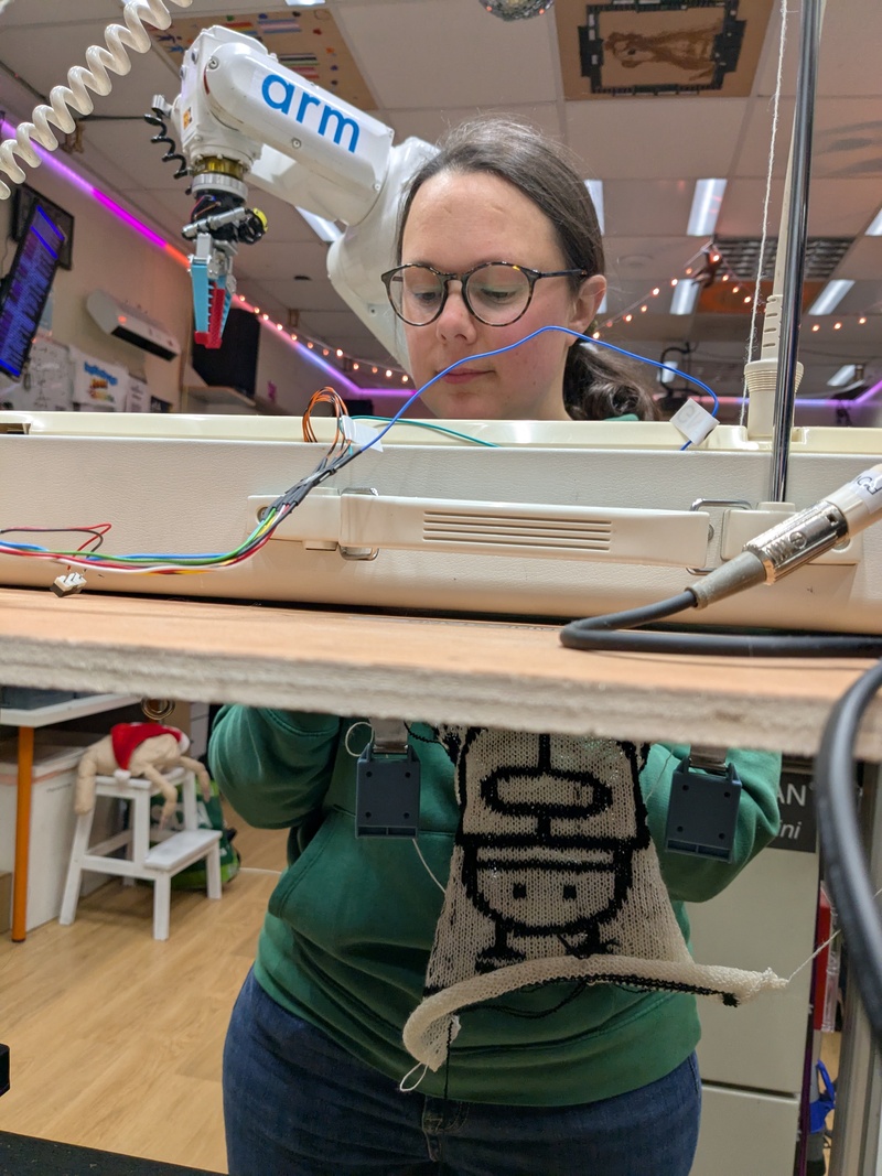
In Edinburgh Hacklab we used this project to let a robot knit a robot- which means they can now reproduce. I don't know of any sci-fi films that have pointed out any downsides to this.
The machine can also now knit pictures - like this:
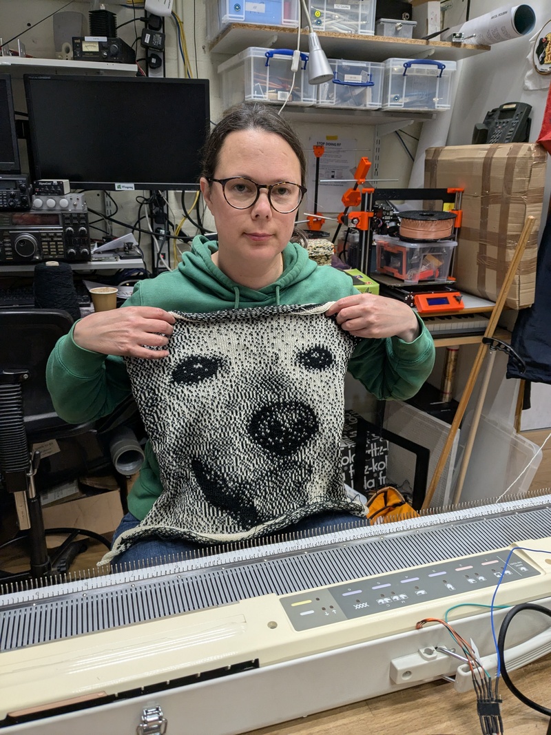
Rosie - The dog at the top of this web page, as knitted by the machine.
Ideally the code would be perfect and easy to use. Unfortunately it's not quite there in terms of code quality and a beautiful, polished interface. It does manage to knit things though, so I'm putting the "quick hack" code out there in the hope that someone finds it useful. As Robin Sloan says: "Work with the garage door open" and all that sort of thing.
If, instead, you like finished, beautiful things I urge you to visit Madeleine Shepherd's site - for knitting machine classes in Edinburgh, Scotland or to purchase some amazing knitted mathematical images and patterns.
Update: Since I wrote the first blog post 6 months ago the AYAB - All yarns are beautiful project has added an experimental Arduino interface for the Knitmaster machines. This might prove to be more mature and supported than this project. This project has a web interface and WiFi however.
The code is freely released under the MIT licence, so do with it as you wish. Get the code here.
Audience for the rest of this post: I'd like to expand this post into a "beginner friendly" tutorial, but until time permits I hope it gives the basic information necessary for someone who is familiar with Micropython and soldering electronics to convert a machine. You will need to be able to work a knitting machine as well, but that seems a whole other level of skill to me! Teamwork and a group of people with overlapping skills is a good thing.
The code is fairly new. "It works for us" but you might need to be prepared to scratch your head a bit and find faults so some experience with this sort of thing would be good.
We developed this hack for an Empisal Knitmaster SK-580 machine. These machines have electronics in the carriage as opposed to the Brother machines which do not. Later Silver-Reed+Knitmaster machines are supposedly compatible but we have not tried any.
The instructions Part1: Building it and converting the machine.
Parts you will need:
- A Raspberry Pi Pico 2 Wireless - These cost £6.60 in the UK. Raspberry Pi Pico 2 W info page.
- Optionally, a 128x64 OLED display (Typically 0.96" or 1.3" size). These are commonly available from lots of online sources (Look for terms like "SSD1306" if confused).
- Some pieces of wire to hook the Pico up to the knitting machine circuit board and display.
- Optionally, a small piezeo speaker/beeper
The Raspberry Pi Pico 1 hardware does not allow 5v input/output hence the choice of the Pico 2. A Pico 1 should work but it will need 5v level converters connected between it and the knitting machine. Such things can be found by searching "5v level converter" or "3.3v to 5v level shifter".
Software you will need:
- The project source code which is available at Codeberg.
- Micropython for the Pi Pico W 2, available from the Micropython Pico2W download page.
- You will need to be able to load the Micropython code to the Pi Pico - software such as Thonny can do this, and there are various tutorials online explaining how to do this.
Step1: Wiring up the hardware
It is possible to wire the Pi Pico straight to a DIN connector which connects directly to the carriage. We tried this originally but didn't get perfect results - there was occasional glitching. An investigation showed that the signals were electrically noisy and there is filtering on the main knitting machine circuit board. Soldering wires directly onto the circuit board seemed to cure this problem, but it does need one wire to be cut.
The machine needs to be opened up. 7 wires need to be soldered on, and a wire cut.
It might be helpful to refer to the Raspberry Pi Pico Pinout diagram which shows which pin is which. The SK-580 service manual is probably also useful.
Machine connections:
It was found to be most reliable to intercept the signals going to the CPU. This makes use of the filtering circuitry on the board, and was done by soldering directly to the CPU pins, as shown in this photo.
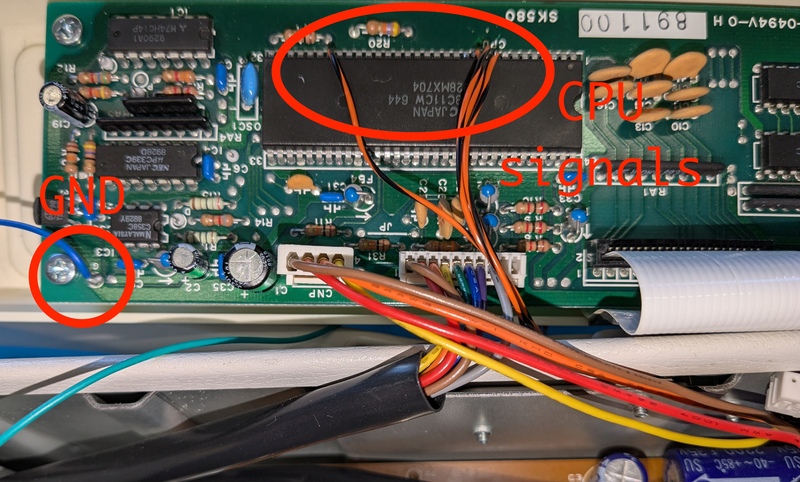
Solder wires from the Pico to the machine board as follows:
| Pi Pico pin | Description | CPU pin |
|---|---|---|
| GP0 | Out - solenoid | |
| GP1 | ND1 | Pin 9 |
| GP2 | In range | Pin 11 |
| GP3 | Clock in | Pin 26 |
| GP4 | Direction in | Pin 10 |
| GND | Gnd (PCB pin) | |
| VSYS | 5v |
GP0 (carrying the stitch control solenoid signal) should be connected to Pin8 of the umbilical cable DIN connector. On our machine this was a grey wire. The grey wire from the original circuit board should be disconnected and placed aside, insulated with a piece of heat-shrink sleeve or similar.
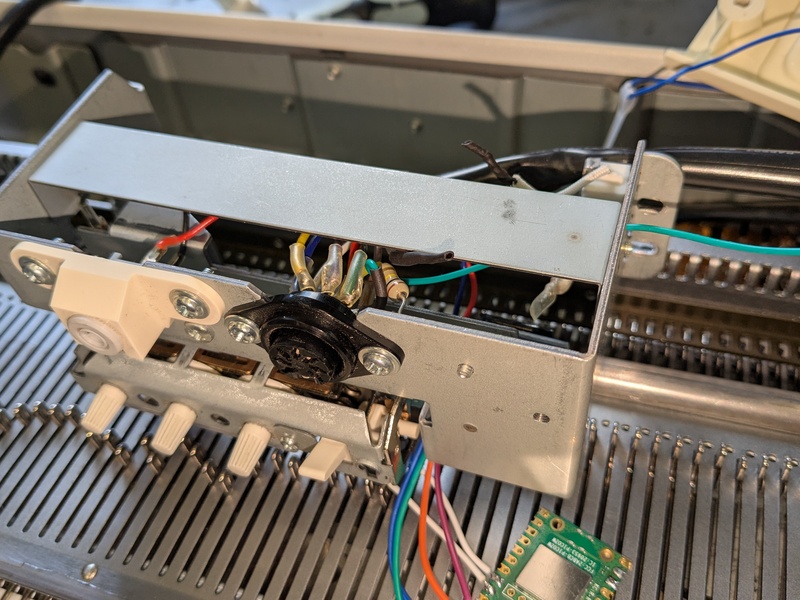 Remove a wire from the DIN connector and solder a replacement which goes to the Pi Pico. This can just be seen in the photo on the right of the connector - our wire has black heat-shrink sleeve.
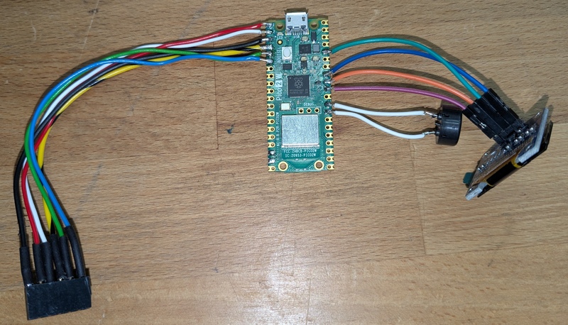 The prototype: Pi Pico with machine connector, beeper and display
Display connections:
Connect the SSD1306 display to the following pins on the Pico:
| Pi Pico pin | Display pin |
|---|---|
| GND | Gnd |
| GPIO26 | SDA |
| GPIO27 | SCL |
| 3V3(OUT) | Power |
Beeper connections:
| Pi Pico pin | Beeper pin |
|---|---|
| GND | either |
| GP22 | either |
Step2: Installing and configuring the software
Download and install Micropython onto the Pico using these instructions.
Download the code from the Git repository.
You will need to edit the file code within 'web interface.py' to allow the Pi to connect to your wireless network. Modify the following lines:
WIFI_SSID="Your SSID Here"
WIFI_PASSWORD="Your password Here"
Install the Micropython ssd1306 driver. This can be done using the "Tools/Manage packages" menu from within Thonny.
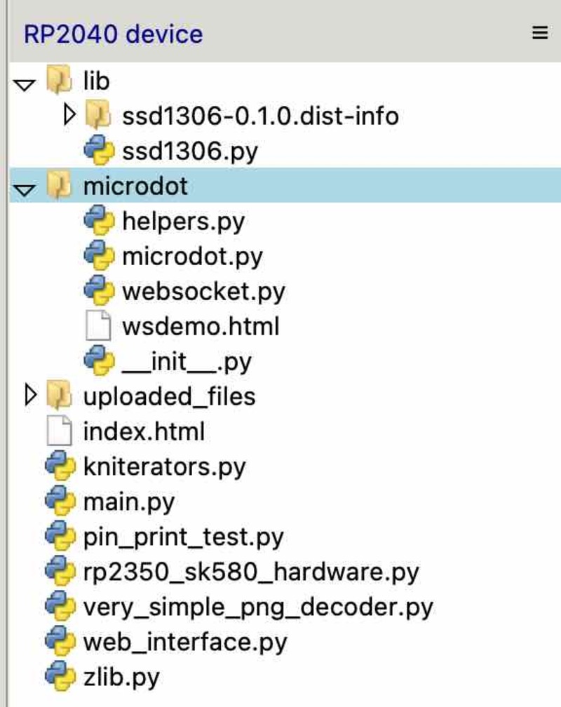
Copy the files from the repository onto the Pi Pico filesystem, including the 'index.html' page. These should all be placed into the Pico root filesystem.
Check: The filesystem should look something like this:
The instructions part 2: Using it
Switch on the machine and look at the display. It should try to connect to the wireless network.
Once it connects it should show an IP address - e.g. 10.23.45.67
Use a web browser on a computer on the same wireless network connect to this IP address - e.g. http://10.23.45.67 (Note - http, not https).
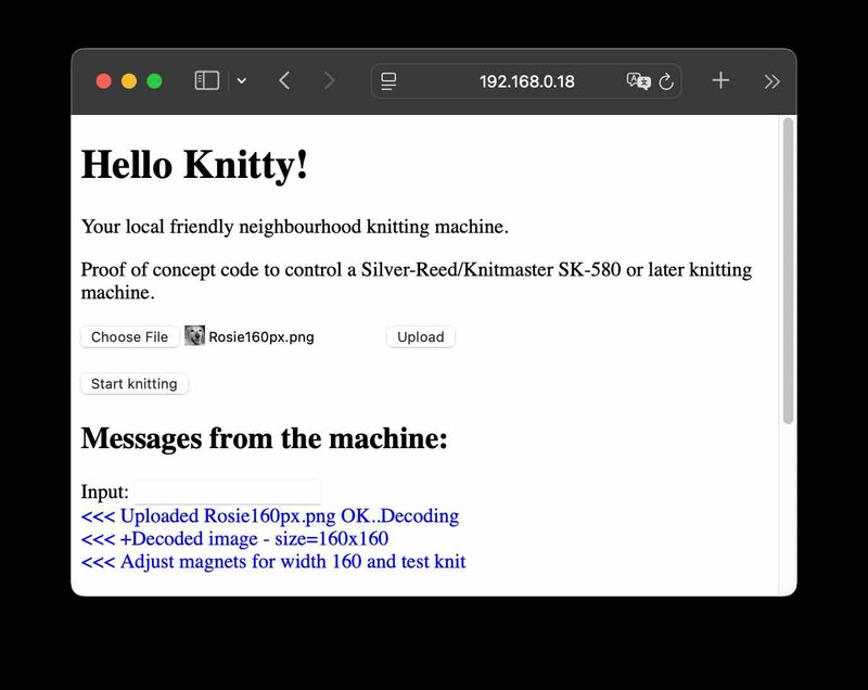
The web interface should display in the web browser:
(Excuse the rather primitive appearance - hopefully this can be beautified over time)
Step 1: Convert an image to black and white.
You need a black and white PNG file with with up to 200 pixels wide. A colour image can be converted using a graphics tool such as the GNU Image Manipulation Program.
- Load the image into GIMP.
- Scale the image to at most 200 pixels wide, using the "Image/Scale image" menu option. One pixel is one stitch.
- Convert to black and white: Select the "Image/Mode" menu. This displays the "Convert Image to Indexed Colours" dialog.
- Select "Use black and white (1-bit) palette, and "Colour dithering: Floyd-Steinberg" and then press the "Convert" button.
- Check that the image looks acceptable. You might need to experiment with contrast and brightness settings.
- Save the image using the "File/Export as" menu option, and enter a filename ending in PNG. Press "Export" when the "Export Image as PNG" dialog is displayed.
If all is well you now have an image that can be loaded into the machine. Cross your fingers!
Step 2: Load the image into the knitting machine.
Going back to the web interface, press the 'Choose File' button and select an image from your computer. Press 'Upload'.
If all is well the web interface should display "Adjust magnets for width xxx and test knit":
- Set the needles on the bed according to the image width (1 pixel = 1 needle) and set the magnets on the bed to match.
- Move the carriage left and right and the detected width should be displayed. If the width is not correct adjust the bed and magnets until correct.
Once the width is correct, cast on and then press the "Start knitting" button.
- The black pixels in the image knit yarn position 1.
- The white pixels in the image knit yarn position 2.
Set the carriage to "F" (Fairisle) mode to knit. When no image is being knitted the machine will knit using position 2 so cast on using the yarn in position 2.
Step 3: Knitting!
Move the carriage left and right (as usual) to knit. The display and web interface should show an arrow to indicate which way the carriage is to move. The display will also update with each line, showing how many rows have been knitted.
It is important to ensure that both sensors on the carriage have passed both magnets on the bed. The beeper should beep to indicate this. Once the beep happens then the next row can be knitted.
Fingers crossed you now have an image! (and most likely also a sore arm. Who needs gym membership when you have a knitting machine?).
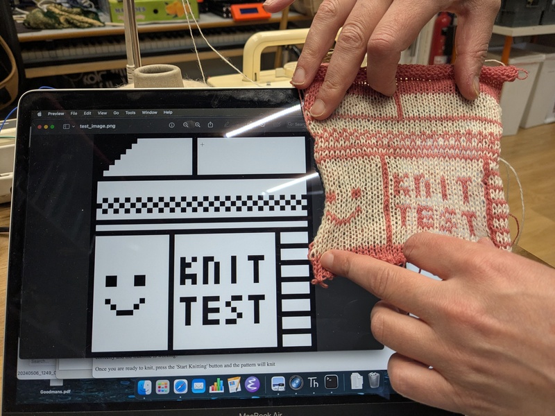
You should hopefully now have a knitted piece which vaguely approximates the image you loaded.
If there are problems: cursing and having a childish tantrum is my usual, calm, debugging technique. These seem essential techniques for fixing both software and knitting machines, so it's good to have a skills overlap. If all else fails: throw the machine in the bin, go out for a walk and fish it out of the bin the next morning.
Slightly more helpfully: The code in "pin print test.py" can be run. This checks that the machine is wired up and shows which signals are coming from the machine.
Fingers crossed all goes well for you.
Some notes which might be helpful:
My earlier blog post talked about how (roughly) the knitting machine and the electrical signals worked.
The first experiments were written using Rust code as I'm more familiar with it for embedded development. I thought that the intersection between people interested in programing in the Rust language and people interesting in knitting machines might be small so decided to re-write the code in Micropython. Hopefully this makes things slightly more approachable.
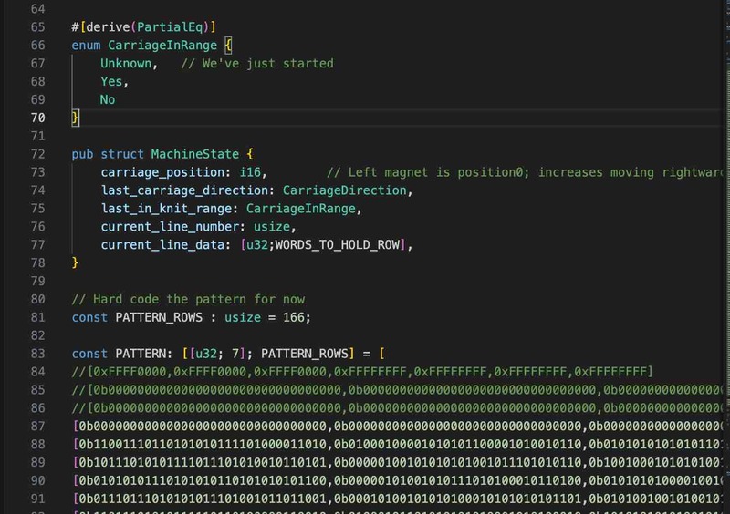
The original code. Writing 1's and 0's by hand in Rust code to represent a pattern is not a friendly interface.
I was interested in learning about the PIO units in the RP2350 processor - these are not necessary for this project, but it was an interesting application to try. Who does not want to make use of the technology of 2025 to have a "Hardware assisted knitting peripheral"?
Allowing the machine to be used standalone with no computer would be nice, so I thought of using a web interface. This can be accessed from a computer or a phone. The Microdot framework - "The impossibly small web framework for Python and MicroPython" looked reasonable so I decided to base the web code around that and it has gone pretty well so far. The file upload code is derived straight from a Microdot example.
At startup, Micropython runs 'main.py' which runs the code in 'web interface.py'. This loads an PNG image using 'very simple png decoder.py' and then talks to the hardware via 'kniterators.py'
I'm sorry to call Python iterators for knitting 'kniterators' but how could I resist?
Kniterators do things such as transform a Python iterator into one which reverses the image with each alternating row. They also provide abstractions to patterns - e.g. to a PNG image or to a text image format.
The RP2350KnitterHardware in 'rp2350 sk580 hardware.py' interfaces between the hardware world and the asyncio Python world. ThreadSafeFlags are used to block asyncio tasks until a hardware interrupt occurs - interrupt handler functions being defined as lambdas in the RP2350KnitterHardware constructor.
The two functions used by the asyncio world for knitting are:
- knitRow() - This takes row data and loads it into the state machine.
- async waitForSMEnd() - Waits until the State machine indicates it has knitted a line
In theory other machines could be supported by swapping out the RP2350KnitterHardware class for another - but the AYAB project already supports the Brother machines so may already support the machines.
The two main parts of the code are both implemented as asyncio tasks:
web_interface.py - check_width_task()
web_interface.py - knit()
Each are only a few lines of code which are hopefully self explanatory.
Enhancements
Some things that could be nice to do:
- Review the "quick hack" quality code and tidy it up for "production quality".
- Improve the documentation and make it easier to install.
- Beautify the web interface and test it for robustness.
- Try it with other knitting techniques/carriage settings.