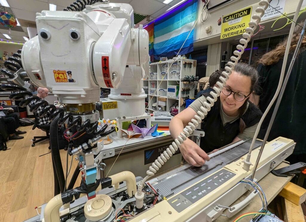
I've Written before about my partner experimenting with knitting machines. Due to reasons which all somehow made sense at the time she ended up acquiring her fourth machine after seeing a post on Freegle and performing some repairs. So, if you've already got one perfectly good knitting machine which is computer controlled the perfectly rational thing to do is to convert another! I thought understanding one of these things enough to control it would be a fun challenge. (Madeleine Shepherd is an artist in Edinburgh who has made some really nice pieces with a similar style of hacked knitting machine. She sells things if you want a cool knitted artwork without the bother of a hacked knitting machine.)
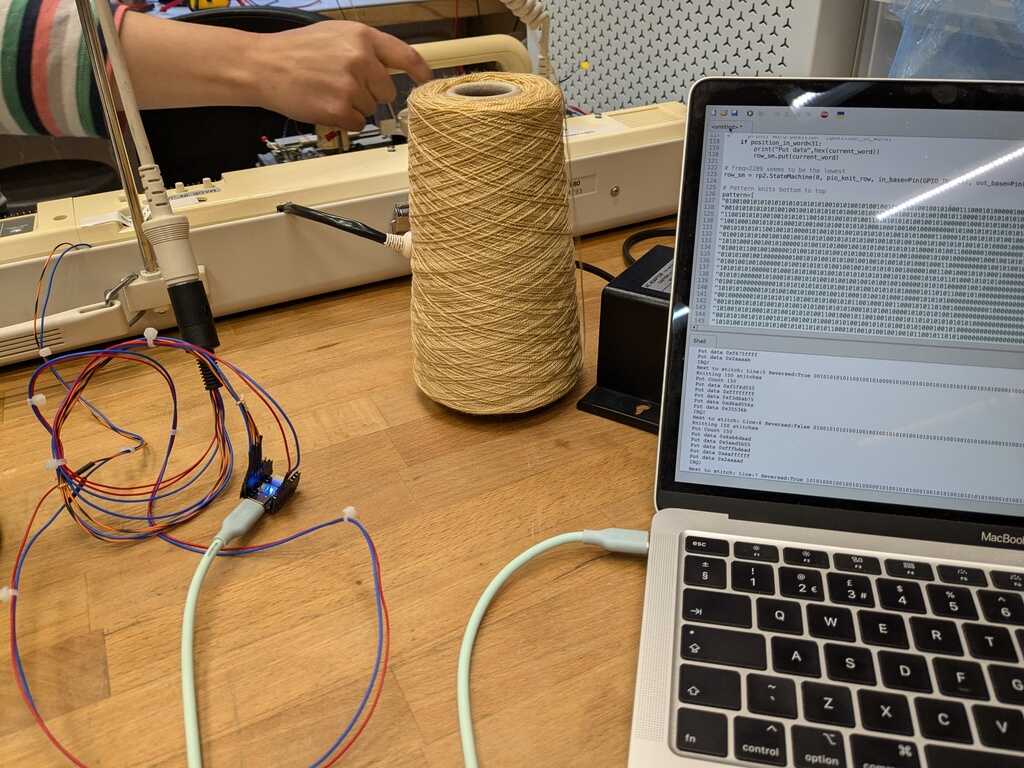
After some experimentation we got a Pimoroni Tiny 2350 to control the knitting machine. It is connected between the carriage of the knitting machine via a specially made cable and a computer via USB-C.
This means we can knit any custom pattern up to 200 pixels wide, similar to the AYAB project for the Brother knitting machines.
How does a knitting machine work?
I began trying to describe this but realised some combination of my lack of writing skills, and lack of knitting-machine understanding skills made this hard. However I really enjoyed Lea Albaugh's talk Languages for 3D Industrial Knitting at the Strange Loop Conference and there is a good animation in there showing how the machine knits - so I point you to this talk.
Roughly, the Empisal KH-580 machine (and most home knitting machines) have a long flat bed containing 200 needles which can slide in and out. To begin a new piece (equivalent to casting on in hand-knitting) a row of yarn is looped by hand over the needles.
A carriage is then repeatedly moved across the bed by hand - pushing forwards, then backwards, and repeating. This carriage lays a new yarn across the bed, and causes the needles to move in and out. These hook the yarn, pulling it through the loops. This makes a new set of loops (called a row) and the previous set of loops/row falls through, and this is knitting.
By allowing different colours of yarn to be selected by the needles coloured patterns can be knitted. This selection is what we control in the project. As there are 200 needles, an image/pattern 200 pixels wide can be knitted.
How does the Empisal machine work?
It is interesting to compare this machine to the Brother KH-910 machine which the AYAB project uses. The Brother electronic machines look to be an evolution of their earlier punched card machines. The electronic mechanism simulates a punched card by means of a number of solenoids - each solenoid covers or uncovers a hole where the punched card would have been. The Brother machines have a belt with holes and counting these holes shows the position of the carriage on the bed.
The Empisal machine is a simpler design which has only one solenoid(*). All the necessary sensors and control mechanism are contained within the carriage. The downside is that the carriage needs an electrical umbilical cable to connect it to the main body of the machine - it is possible that this cable gets in the way. But this is attractive for hacking as it means we can control the whole machine just by plugging this cable into our own electronics, and do away completely with the electronics in the machine.
(*) Note: The mechanism is actually duplicated - one side does the right to left direction and the other side is a mirror image. So there are actually two solenoids.
The carriage of the machine has a combination of hall-effect sensors (which detect the presence of magnets) and infra-red sensors (which detect a break in a beam of light) to tell it where it is.
The basic idea is:
- Figure out the position of the carriage on the bed.
- Look up the colour that is to be knitted for this position in the pattern.
- Feed a signal to the solenoid on the carriage to select the colour.
- Wait for the carriage to move to the end of the row, and start knitting the next row in the pattern.
Fortunately, the KH-580 service manual is available online, which made it much easier to figure out how it works.
Pages 31 and 32 are the most interesting, as they tell us what signals are carried in the umbilical cable. Some of the descriptions weren't completely clear ("The PCP 0utput signal is obtained from a value with the infrared ray passing through the PCP Clock Plate") and it took a bit of experimenting and measuring with an oscillocope to figure it all out.
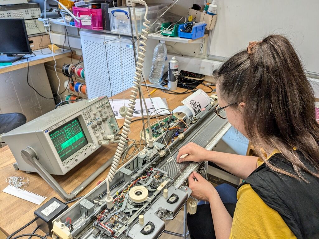
We made cards with a variety of simple patterns and compared the carriage to and from the carriage with the pattern to understand how the sensor signals and output were encoded. We determined that the cable has the following signals:
- Pin 1: ND1 - The "Needle 1" signal. Signals when the carriage has passed a special marker magnet. I'm not completely sure what this is used for but believe it allows the operator to have a pattern that is not positioned in the middle. It's currently ignored in this project.
- Pin 2: KSL - Signals that the carriage is "in range" of the pattern markers. 0 = Out of range, 1 = In Range
- Pin 3: DOB - Output to the solenoid to control which yarn to use. 0 = Black pixel on pattern, 1 = White pixel on pattern.
- Pin 4: CCP - This signal pulses once per stitch as the carriage moves across.
- Pin 5: HOK - Direction. 0 = Moving to the left, 1 = Moving to the right
- Pin 6: 16v - Used to power the solenoids.
- Pin 7: 5v - Used to supply the logic on the board.
- Pin 8: GND
The logic signals are connected directly to GPIO pins of the Pi Pico. Fortunately the newer RP2350 chip has 5v tolerant signals so no level conversion is needed. (This isn't the case with the older RP2040 chip).
The Micropython code
The Python code operates as follows:
- A PNG file containing the pattern is read from the filesystem. I used the code described in Writing a simple PNG decoder might be easier than you think as a basis.
- The data for the current row is written to one of the PIO state machines (and reversed if necessary - the machine knits backwards when moving from right to left). The main Python code waits for an interrupt from the PIO to signal it has reached the end of the row and wants more data.
- This repeats until the final row is knitted, at which point the program stops.
The PIO
The PIO in the Raspberry Pi is a really interesting peripheral. It has its own special instructions and the Micropython interpreter allows PIO programs to be written from within Python. This is the code that does the knitting:
# PIO program to take a row of stitches and send them out to the solenoid with every clock, when in knitting range
@rp2.asm_pio(set_init=(rp2.PIO.OUT_HIGH,rp2.PIO.OUT_HIGH,rp2.PIO.OUT_HIGH),
         out_init=rp2.PIO.OUT_HIGH,
         out_shiftdir=rp2.PIO.SHIFT_RIGHT,
         fifo_join=rp2.PIO.JOIN_TX)
def pio_knit_row():
  # For debugging indicate LED red to show we're waiting for a stitch count
  set(pins,0b110)
  # Firstly, get the number of stitches and store it in Y
  pull(block)
  out(y,31)
  # Turn the LED green to show we're ready and waiting to go into the stitch area
  set(pins,0b101)
  # Now wait for the in range (GPIO2) to go high indicating we've to start
  wait(1,gpio,2)
  # This loop pulls a 32 bit word
  label("word_loop")
  # Turn the LED magenta to show we're waiting for a word from the main CPU
  set(pins,0b010)
  # Now we need to get a word from the main CPU
  pull(block)
  # and turn the LED blue to show we're shifting it out and hopefully knitting
  set(pins,0b011)
  # In this loop we need to shift out a whole word - 32 bits-1 so count this in X
  set(x, 31)
  label("bit_loop")
  # Decrement the stitch counter (Y)and go to the end if we're finished
  jmp(y_dec,"stitch_bit")
  jmp("row_end")
  label("stitch_bit")

  # Wait for the clock pin (GPIO3) to go high
  wait(0,gpio,3)
  wait(1,gpio,3)
  # Shift out a stitch bit to the solenoid (1=output 1 bit to 1 GPIO)
  out(pins, 1)
  # And continue if we're still got bits in this shift register word
  jmp(x_dec,"bit_loop")
  # ..and now jump to pull another word of stitches
  jmp("word_loop")
  label("row_end")
  # Wait for us to go out of range before notifying the processor
  wait(0,gpio,2)
  irq(block,rel(0))
  # and will now loop to the top ready for the next row...
Testing it out
I prepared a test image...and it worked! Unfortutely these machines knit back-to-front so the best way to see the image coming out is under the table, so apologies for the slightly strange angle.
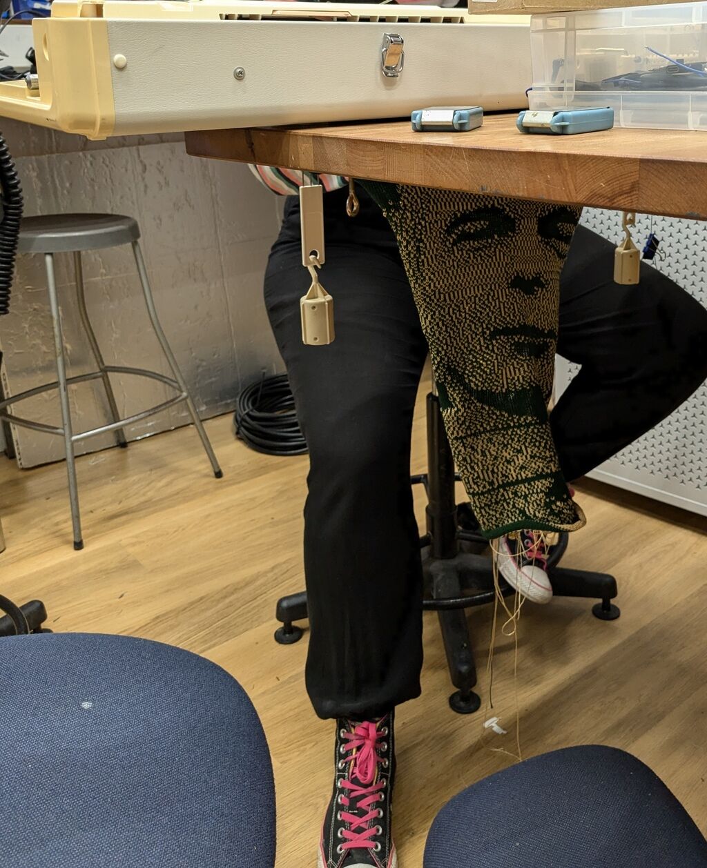
I used the GNU Image Manipulation Program/GIMP to convert the image from colour into a one bit image the machine could knit. For reference, the menus are: Image/Mode/Indexed and then enable Floyd-Steinberg dithering. Some experimentation with photos and levels are necessary - we still need to learn which makes the best patterns.
The Robot
We did all this in the Edinburgh Hacklab - who have an unused industrial robot arm. Of course, never make jokes like "Wouldn't it be cool if we got a robot to do this"....because, of course, it was generally agreed that this was a stupid idea and therefore we should do it.
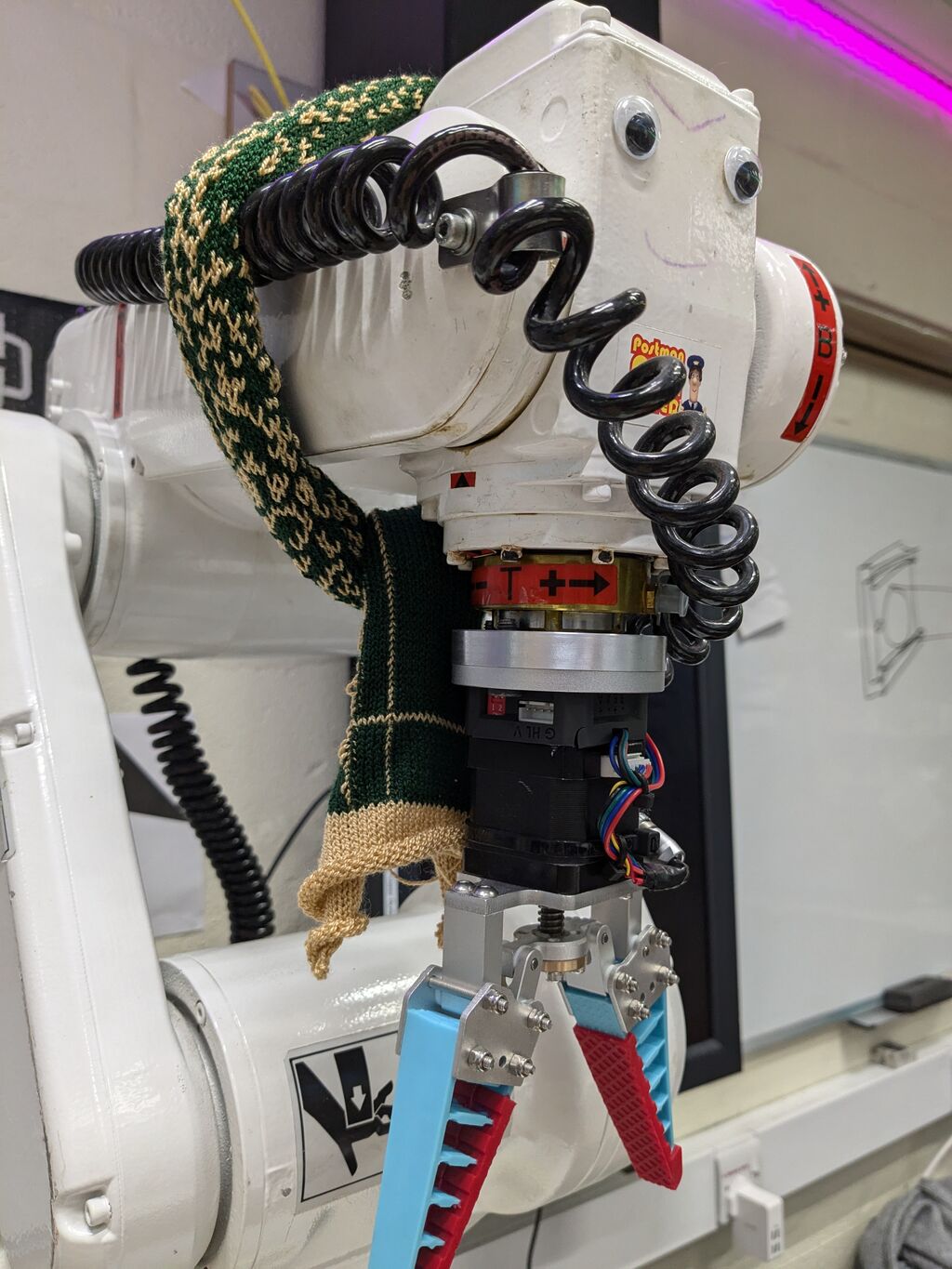
Unfortunately the first prototype used a single solid core wire, as this was lying around. The shaking caused by the robot movement caused this wire to break - which resulted in the robot knitting junk. However, I rather like the accidental "glitch art" scarf the robot knitted for itself!
I think the robot looks quite happy too...
Next steps
I'm not sure if this project is interesting or not, but perhaps I can tidy up the code a bit and publish it if there is interest.